
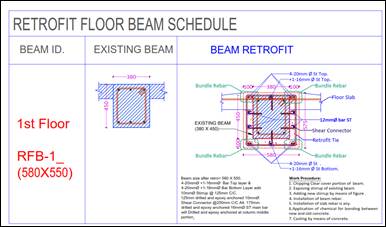
RC BEAM RETROFIT – INTERFACE SHEAR TRANSFER DESIGN
Three-Sided RC Jacket (100 mm) | Hilti Method (Palieraki, V., Vintzileou, E., Trezos)
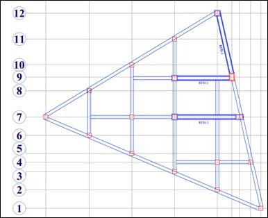
Beam: b0 = 380 mm, h0 = 450 mm | Zone = L/4 = 1.50 m | Dowels: 2-10mm @ 12″ c/c each side
Ab = pi/4 x db² = pi/4 x (0.3937)² = 0.12174 in²
Avf = n x Ab (n = 10) = 10 x 0.12174 = 1.21737 in²
le / db = 3.9370 / 0.3937 = 10.00
le/db = 10.00 > 8.0 → SATISFIED → bd = 0.7 applicable (static)
Ac,bottom = b0 x (L/4) = 14.9606 x 59.055 = 883.50 in²
Ac,side (each) = h0 x (L/4) = 17.7165 x 59.055 = 1046.25 in²
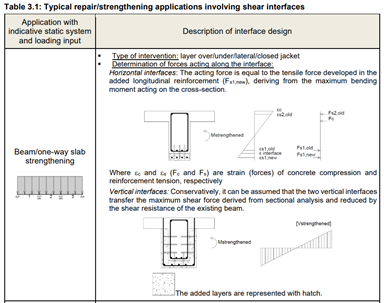
Vn = Ac ( bf x tf + bd x td ) phi Vn ≥ Vu, phi = 0.75
| Parameter / Condition | Value |
| bf — mech. roughened, normal conc. (<8 ksi), static | 0.6 |
| bd — le > 8 db, static | 0.7 |
First term fy Avf / Ac = 60,000 x 1.21737 / 883.50 = 82.673 psi
Second term 5 fbu le Avf / (db Ac) = 5 x 1,000 x 3.9370 x 1.21737 / (0.3937 x 883.50) = 68.895 psi
fc,vf = MIN(first, second) = MIN(82.673 , 68.895) = 68.895 psi
First term fy Avf / Ac = 60,000 x 1.21737 / 1046.25 = 69.813 psi
Second term 5 fbu le Avf / (db Ac) = 5 x 1,000 x 3.9370 x 1.21737 / (0.3937 x 1046.25) = 58.178 psi
fc,vf = MIN(first, second) = MIN(69.813 , 58.178) = 58.178 psi
(f’c)² x fc,vf = (3,000)² x 68.895 = 620,051,181.6
Cube root […]^(1/3) = [620,051,181.6]^(1/3) = 852.725
tf = 0.33 x 852.725 = 281.399 psi
(f’c)² x fc,vf = (3,000)² x 58.178 = 523,598,775.6
Cube root […]^(1/3) = [523,598,775.6]^(1/3) = 805.996
tf = 0.33 x cube root = 0.33 x 805.996 = 265.979 psi
sqrt(f’c x fy) = sqrt(3,000 x 60,000) = 13416.408
Numerator 1.3 x 10 x db² x sqrt(f’c fy) = 1.3 x 10 x 0.15500 x 13416.408 = 27034.116
td = numerator / Ac = 27034.116 / 883.50 = 30.599 psi
td = numerator / Ac = 27034.116 / 1046.25 = 25.839 psi
vn = bf tf + bd td Vn = Ac vn phiVn = 0.75 Vn
bf x tf = 0.6 x 281.399 = 168.840 psi
bd x td = 0.7 x 30.599 = 21.419 psi
vn = bf tf + bd td = 168.840 + 21.419 = 190.259 psi
Vn = Ac x vn = 883.50 x 190.259 = 168.094 kips
phiVn = 0.75 x 168.094 = 126.070 kips > 116 kips, Therefore OK.
bf x tf = 0.6 x 265.979 = 159.587 psi
bd x td = 0.7 x 25.839 = 18.087 psi
vn = bf tf + bd td = 159.587 + 18.087 = 177.675 psi
Vn = Ac x vn = 1046.25 x 177.675 = 185.892 kips
phiVn = 0.75 x 185.892 = 139.419 kips for one side, for two sides phiVn = 278.8 kips. > 100 kips, OK.
Factored shear demand: Vu = 116.64 kips (applied over L/4 zone interface)
| Interface | phi Vn (kips) | Vu (kips) | UCR = Vu/phiVn | Status |
| Bottom interface | 126.070 | 116.64 | 0.925 | PASS |
| Each side interface | 139.419 | 100.00 | 0.837 | PASS |